Development of Natural Draft Gasifier for Steam Generation


ABSTRACT
In India, fuel wood continues to play an important role both in domestic and industrial sector. It is estimated that about 7 to 10% of the total fuel wood consumption is in rural industries and village applications.
Biomass gasifier can be utilized in providing the rural energy needs like lighting, irrigation, water pumping along with the energy requirements of rural agro based industries. This will also be helpful in providing a sustainable solution to rural energy problems. Biomass is available in almost all the villages and its utilization for generation of electricity will not only increase economic activities in villages through decentralized biomass power plants but also would be helpful in the development of the area leading to general prosperity of the rural people.
There is scope to introduce wood based gasifier with steam generator instead of conventional ‘chulha’ and diesel/kerosene boiler in small agro-industries. Keeping these points in mind, natural draft gasifier is developed by department of bio energy, Tamilnadu agricultural university. Natural draft gasifier does not require electricity for operation. Capacity of gasifier is 10 kg/h. Performance evaluation study was carried out on the system.
Flame temperature of gas was found to be 630ºc. The mass and energy closure was found to be 93.73% and 78 % respectively.
Introduction
Steam is a vital part of the agro processing industry. It is used, both directly and indirectly, for heating, cooking, sanitizing, and sterilizing. The advent of the industrial revolution provided the impetus for the large scale processing of food. Steam was used as the medium. It was easy to produce and simple to transport at different places. Hence steam was taken for granted and no thought was given to improving the ways in which it can be used alternatively. The present method of steam generation is not hygienic and energy efficient. Identifying this area of concern, gasifier was developed and tested in Department of Bio Energy, Tamil Nadu Agricultural University, and Coimbatore.
Materials and Methods Natural Draft Gasifier System Description
Reactor
Reactor of the gasification system is a cylindrical structure. The inside of this is insulated with fire bricks lining.
Grate
A Grate is provided at the bottom of gasifier for material support and ash removal.
Grate agitator
A grate agitator was provided to move to and fro on the channel guide with the help of the handle. Due to the movement of the agitator, combing action on surface of the grate takes place, to remove the ash accumulated on it.
Air inlet
Air inlet pipe is provided below the grate. The air pipe is having valve to control the air Supply to the gasifier.
Ash removal port
An ash removal door is provided below the grate for removal of ash and for firing of biomass while starting the gasifier.
Biomass feeding hopper
Biomass feeding to the gasifier is done from the side of the reactor. A hopper attached to the reactor is tapered and biomass is fed through the pipe to the reactor.
Sealing of biomass
A water seal at the opening of the biomass feeding hopper is provided.
Gas outlet
The gas generated in the reactor moves upward through a perforated plate having holes on the plate.
Burner
The gas burner is an integral part of the gasifier fitted just above the reactor. The producer gas burner is of aspirated and air swirling type. The swirl was noticed during the burning of the gases. The control of the air to the burner was provided using the valve fitted for the air supply.

Performance Evaluation of the Gasifier
Gasifier is tested for performance studies. Before that, properties of feedstock used were studied.
Gasifier efficiency Calculations
i) Temperature Profile of the Reactor
The temperature profile of the gasifier is measured using chromel-alumel thermocouples at 4 different locations i.e. at the 20 mm, 120 mm, 320 mm and 720 mm above the grate. The digital Temperature indicator measures the temperature inside the gasifier.
ii) Flame Temperature
The flame temperature of the gas burning in the developed burner is measured using Thermocouple (chromel-alumel) with temperature indicator. While measuring the temperature; air drift to the burner can be avoided. The maximum temperature of the flame is measured by shifting the thermocouple to different locations of the flame.
iii) Water boiling and Evaporation test
The most commonly used indicator to express the performance of the natural draft gasifier is the “Water Boiling & Evaporation Test”. It is a measure of the extent of energy of the fuel burnt for the purpose of steam generation and may be expressed in the ratio of the heat used for the boiling / evaporation of water to the calorific value of the fuel consumed. The controlled water-boiling test is performed to estimate the time taken for boiling under fixed rate of charging of the fuel.
Results and Discussion
Temperature profile in the reactor and flame temperature
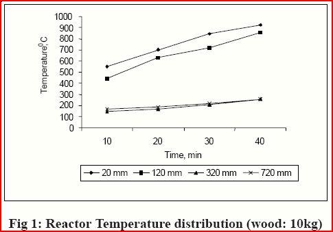
Fig.1 gives the temperature profiles set up across the reactor in 10 kg trial with wood chips as feed material. Near the grate, temperature is gradually established upto a maximum of 923ºC. Temperature as high as 550°C can be reached in duration of 15-20 minutes near the grate and the gas temperature noted is 360°C. The temperature profile was found to fluctuate widely at different heights of 20 mm, 120mm, 320 mm and 720 mm above the grate.

The flame temperature measured at the exit of burner was found to vary from 360-603ºC
(Fig.2).

Smoke temperature measured at the opening of chimney was found to be ranging from 136-156ºC (Fig.3). It indicates that all the heat generated was utilized. Inlet air temperature was measured at the opening of inlet pipe. Inlet air temperature was found to be in the range of 30.5- 32.2ºC (Fig.4).

Overall thermal efficiency of gasifier
The overall thermal efficiency of gasifier burner system is evaluated by boiling test as stipulated by BIS for thermally efficient wood burning stoves. The overall efficiency of gasifier was found to be 17.21% (by water boiling test) which was much higher than that of efficiency of conventional chullas (10.22%) and the output of gasifier has worked out to be 24350 kcal/h (thermal). The power rating is nearly 30KW.
Mass and Energy balance of system
Mass balance is arrived at by measuring various inflow and outflow of materials; while energy balance can be calculated on the observation of energy content, temperatures of reactor etc. The mass closure was found to be 96.73%. Energy closure was 78 %.
Conclusion: -
1. Ability to use Agricultural Residues at High Efficiency
2. Fuel wood declining
3. Ag crops increasing, Urban/Village wastes growing problem
4. Future Systems have to make Productive Use of Heat
5. All systems are heat engines
a. Turbines and Sterling concepts can produce high quality heat
6. Environmental Performance Improvements are needed for
a. GASIFIERS-IC Engines
7. Overall system performance with respect to
a. Air emissions - Nox, CO and particulate
b. Water emissions - particulate, tars, and phenols
8. Advanced Technologies
9. Increased efficiency
10. Potential synergy with automotive and other developments to
11. Reduce costs of Energy.
No comments:
Post a Comment